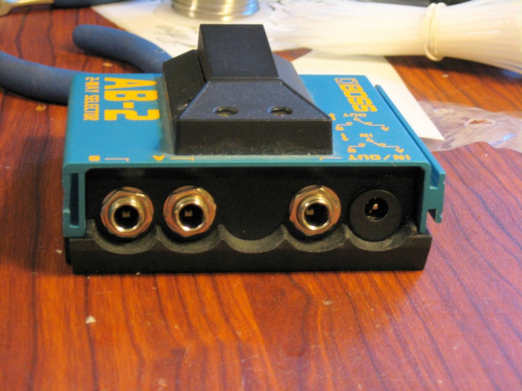
The Boss AB2 is a relatively inexpensive and readily available buffered A/B footswitch. It suffers from one critical problem: it cannot be powered by a pedalboard supply. Boss decided to make this pedal run only from a pair of AAA batteries stored inside the unit, which must be disassembled to change. And if the batteries die, no sound gets through because it’s a buffered pedal. Because of these problems, the AB2 is a rare sight to see on pedalboards, but that can be fixed with just a few parts and a few minutes of work.
Modifying this footswitch to run from a standard 9V DC pedalboard supply is fairly simple. The parts needed are:
- Insulated plastic DC power jack (like this one) – metal jacks will NOT work!
- Two 680 ohm 1/2-watt resistors
- Three inches of 20-gauge stranded wire
- (Optional but not recommended) 9V battery connector
The tools needed are:
- #1 Philips screwdriver
- Jeweler’s Philips screwdriver
- Needle nose pliers or 1/2″ hex socket (to remove nuts from 1/4″ jacks)
- Wire snips/strippers
- 1/8″ drill bit
- 1/2″ Uni-bit (like these)
- Soldering Iron
- (Optional) center punch
- (Optional) High-speed rotary tool with carbide cutter to clean up drill hole
- (Optional) voltmeter or multimeter
Getting Started
Remove the hex nuts on the three 1/4″ jacks. Remove the two screws on the back and open the case. Remove the 2xAAA holder and unsolder the two wires from the PCB. Remove the two screws that hold the PCB to the case. The PCB should now be removable, but leave it in place for the moment.
There is a free space in the case that is just the right size for a DC jack. There is just enough space to fit the jack, but we have to be careful to choose our center point wisely. If it’s too close to the PCB, we won’t be able to reinstall the board. If we’re too close to the bottom of the case, the metal securing nut won’t be able to fit. Eyeball for a spot evenly centered between the PCB and the bottom of the case, and if you have a center punch, use it to mark the spot. Now, remove the PCB from the case.
Breaking Stuff
On the underside of the PCB, near where our power jack is going to go, there’s a little black electrolytic capacitor. Mine was laying down across the PCB and would have blocked the jack from going in, so I carefully stood it up, then bent it down alongside the input jack. This provided the necessary clearance for the jack and PCB to coexist.
With the 1/8″ drill bit, drill the hole marked in the last step. Then use the 1/2″ Uni-bit to slowly widen the hole all the way to 1/2″. My plastic jack was just the slightest bit larger than 1/2″, so I used my dremel to carefully clean up around the drill hole and open it just enough for the jack to go through smoothly. Put the securing nut in place. Due to the tight clearance with the bottom of the case, you may need to spin the power jack in order to tighten the nut.
Burning Fingers
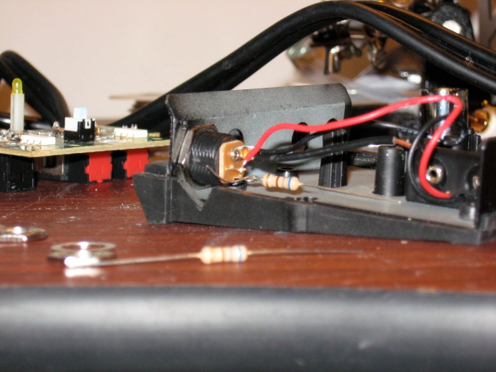
Now, solder your short length of 20-gauge wire to the tip lug on the jack. Solder a 680-ohm resistor to the sleeve lug. Optionally, you can install a 9V battery adapter by hooking the black to the tip lug and the red to the momentary sleeve lug. If in doubt, see the picture on the link above to the DC power jack. Bend the black wire and 680-ohm resistor so they stick out the side of the case.
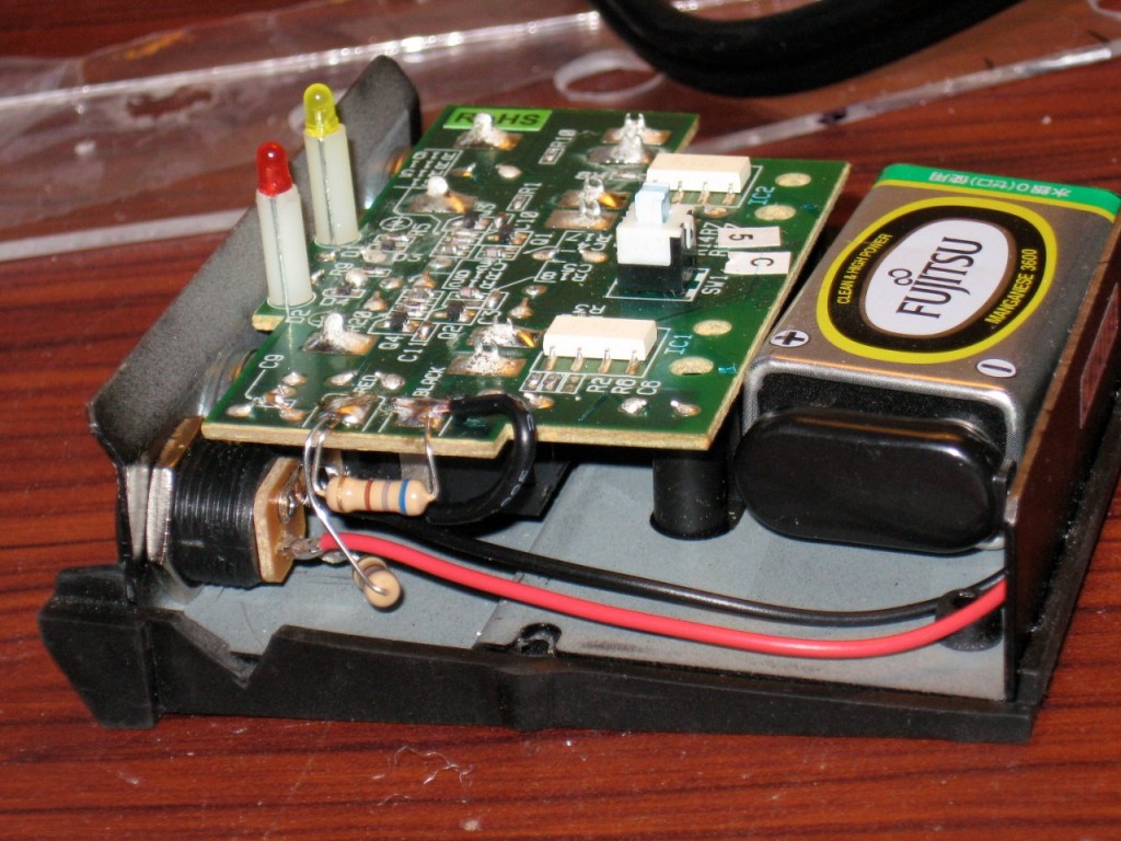
Reinstall the PCB. You can install the two PCB screws and three hex nuts now. Take your second 680-ohm resistor and bend its leads as shown in the photos below, so the leads sit naturally on the PCB’s “RED” and “BLACK” soldering pads. Route the black wire down past the notch in the PCB, then back to the “BLACK” pad. Solder the black wire and resistor to the “BLACK” pad. Now, bend the 680-ohm resistor from the DC jack up so its lead lays naturally on the “RED” pad. Make sure there is enough clearance so this resistor does not touch the case when it is reinstalled. Solder the 680-ohm resistors to the “RED” pad.
Testing
This circuit was designed to run at about 3V. Prior to hacking up the pedal I measured the voltage with two AAAs and the input jack inserted at 2.6V. If you installed a 9V battery connector, plug in a 9V battery and measure the voltage across the “RED” and “BLACK” soldering pads. You should read about 4.5V with nothing plugged into the pedal. Now plug in a cable to the input jack, so the pedal powers on. Recheck the voltage. With a fresh battery I measured 2.7V. Now, plug in your pedalboard supply and measure the voltage. I measured 2.8V. Anything from 2.5 to 3.3V will be adequate. I’ve been running mine like this for over two years and it hasn’t burnt out yet.
We’re all done! Close the case and reinstall the two screws on the bottom.
About the 9V battery
Although I included instructions for including the 9V battery connector, I don’t recommend installing one. Due to the 680-ohm resistor sitting between the red and black pads, a 9V battery left in this pedal (even when off) will be discharged within a few days. Maybe someone else can suggest a way to wire the plug so the battery is unloaded when no DC jack is plugged in.

