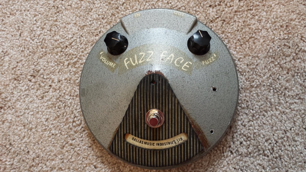
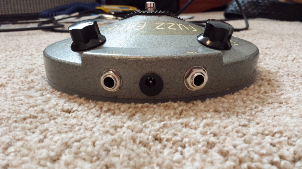
My friend’s dad picked up this Dallas Arbiter Fuzz Face new in 1976. It came as an NPN silicon circuit with BC209 transistors, and after 30 years of component drift it sounded downright horrible. He tried gutting the thing and shoving a Boss SD-1 board inside, but that didn’t work out. By the time the thing got to me it was a beaten chassis with no back plate, extra holes drilled in the front, all jacks, pots and switches missing, and a broken indicator LED. The original circuit board was there but it was a lost cause.
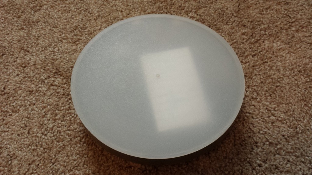
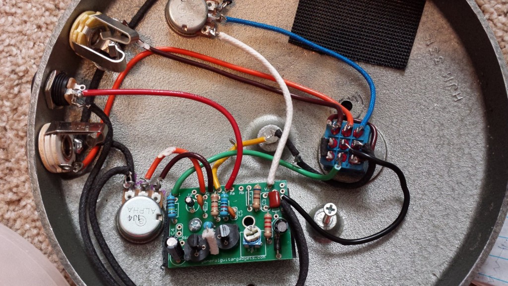
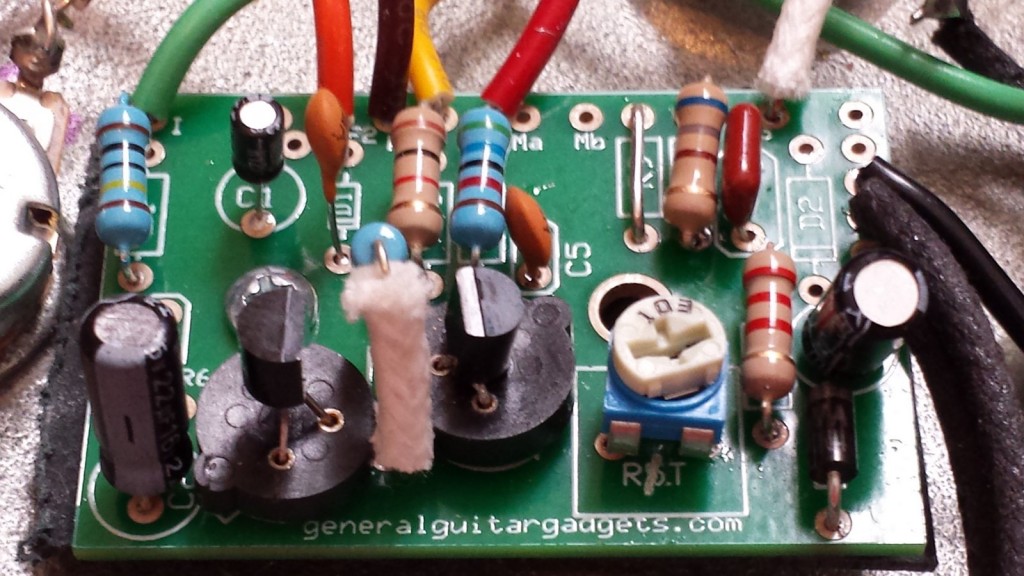
I set out to rebuild this pedal to be what it was intended to be – an NPN Silicon Fuzz Face – but with a few circuit improvements to make it work the way he wanted. I went with a new PCB from http://www.generalguitargadgets.com/ that allowed for transistor sockets and a few added parts. I picked up a cheap kitchen cutting board at Wal-Mart and chopped it into a new rear panel with the help of a dremel tool, a routing bit, and the circle cutting attachment. To maintain the stock look as much as possible I left the faded old red LED lens cover in place and hot-glued a high-intensity white LED into it.
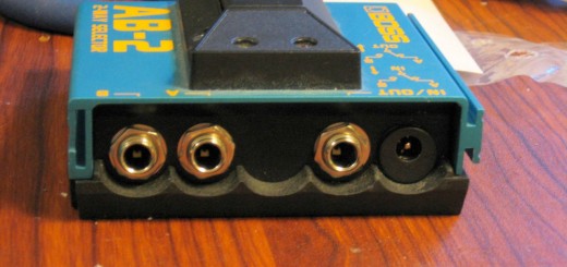
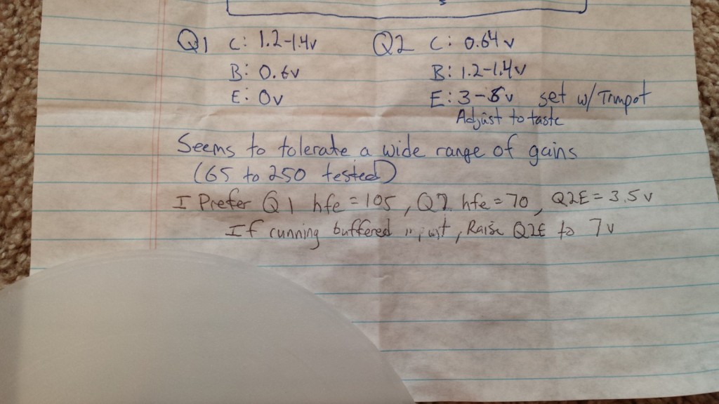
Since he ALWAYS plays with a pedalbaord, I added a DC power jack and removed the battery connector. I added the optional diode and capacitor to filter any additional switching noise coming from the power supply. I also added the 1M anti-pop ground reference at the input and a 5K trimpot to adjust Q2′s bias point. Otherwise I built out the circuit according to the standard NPN Silicon build (http://www.generalguitargadgets.com/projects/73-fuzz-tones/101-fuzz-faces). I ordered a bunch of NPN Silicon transistors and sorted through them to find ones with reasonable gain levels.
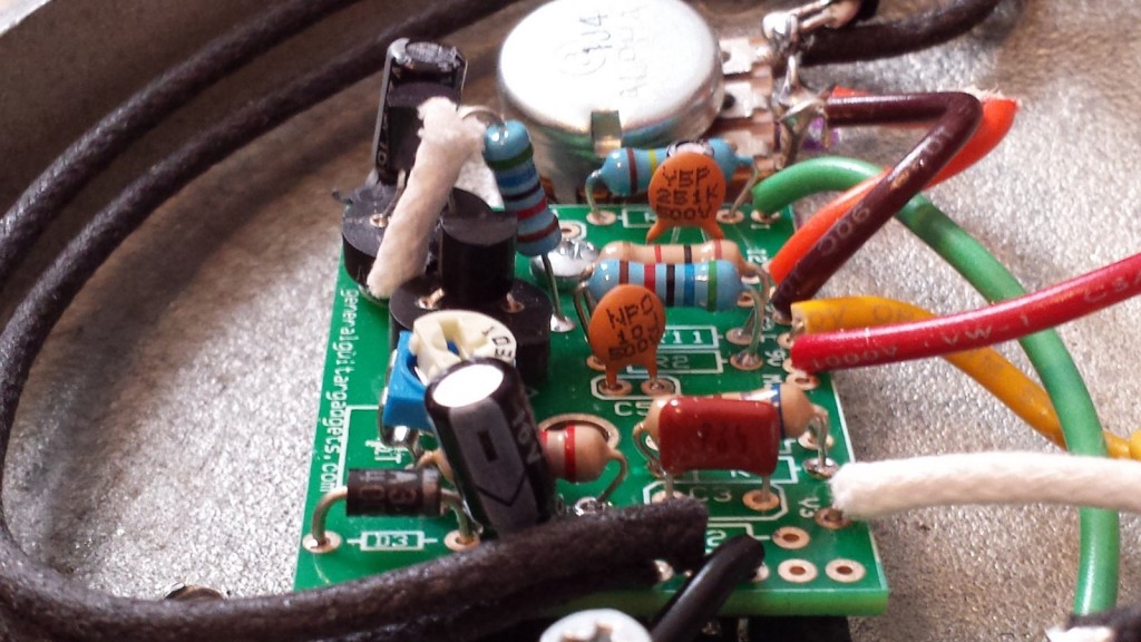
In the original circuit, I couldn’t get Q1 or Q2 to bias anywhere near the right operating points. I pulled out a bunch of resistors and replaced them with potentiometers to tune up the right values. The most critical changes were increasing R2 from 33K to 56K and reducing R3 from 100K to 56K. I wasn’t getting enough adjustability from the 5K trimpot so it got replaced with a 10K version. I increased R4 from 330 to 680 ohms to compensate for the greater resistance at the trimpot- without this change the maximum volume was less than unity gain when using an unbuffered input.
With the circuit now biased and operating correctly I tried it out with a bunch of different transistors. All of them gave a harsher clipping than I wanted. After looking at some forum posts on the internet I decided to try a very small capacitor in the C5 slot and also a 250pf cap in the D1 slot. With this combination and some low-gain transistors I got the unit sounding pretty good, so I didn’t experiment with any other values.