One day my friend Frankie picked up a Hammond M103 organ from the side of the road. It didn’t work, but all the parts were there. After looking at how much work it would take to get it running again, he stripped all the useful parts and gave them to me.
This project is NOT made from the Hammond organ parts. Well, not exactly.
The Pile of Parts
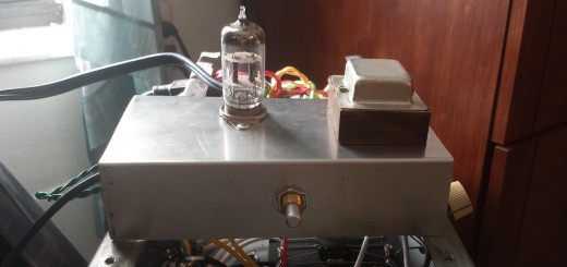
There was this strange device in the pile of Hammond stuff… A 4″ x 6″ chassis, two transformers, three tubes, and a 2.5″ speaker. The circuitry was bizarre, and although it powered up, it didn’t seem to work. After digging through and mapping out the circuit I figured out it was supposed to be some sort of relay-switched audio monitoring device, like the receiving end of a 1-way intercom. Trouble is, whoever put this thing together never quite figured out how to get the relay portion to work.
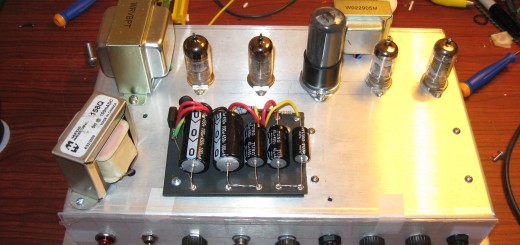
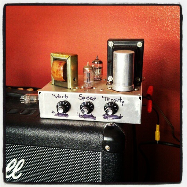
So here I am with a chassis, an Allied 6K49VG power transformer (460v @50ma, 6.3v @2.5a), an Allied 6-W-48-VF single-ended output transformer, a 6T9 compactron tube, a 12AU7, and a 2D21 (relay tube). Pretty quickly I decided to ditch the 2D21 and 12AU7, replacing them with a 6C4 triode and a 12AX7. With three high-mu triodes, one low-mu triode and a beam power pentode I knew exactly what to build – A simpler, compact “Revibe” – a reverb and tremolo effect unit!
There was a perfectly good (if not slightly wierd) power circuit in place so I left it alone. A two-diode rectifier setup ran in through a pair of fuses before taking a 1K resistor to the first capacitor. I guess this acts like a poor man’s inrush limiter. Also very interesting is that the ground plane for the RC filter network was lifted by a 1K resistor and a 50/50 electrolytic cap from chassis and circuit ground. I hadn’t seen this done before, but it proved to be an effective and quiet arrangement.
The Reverb
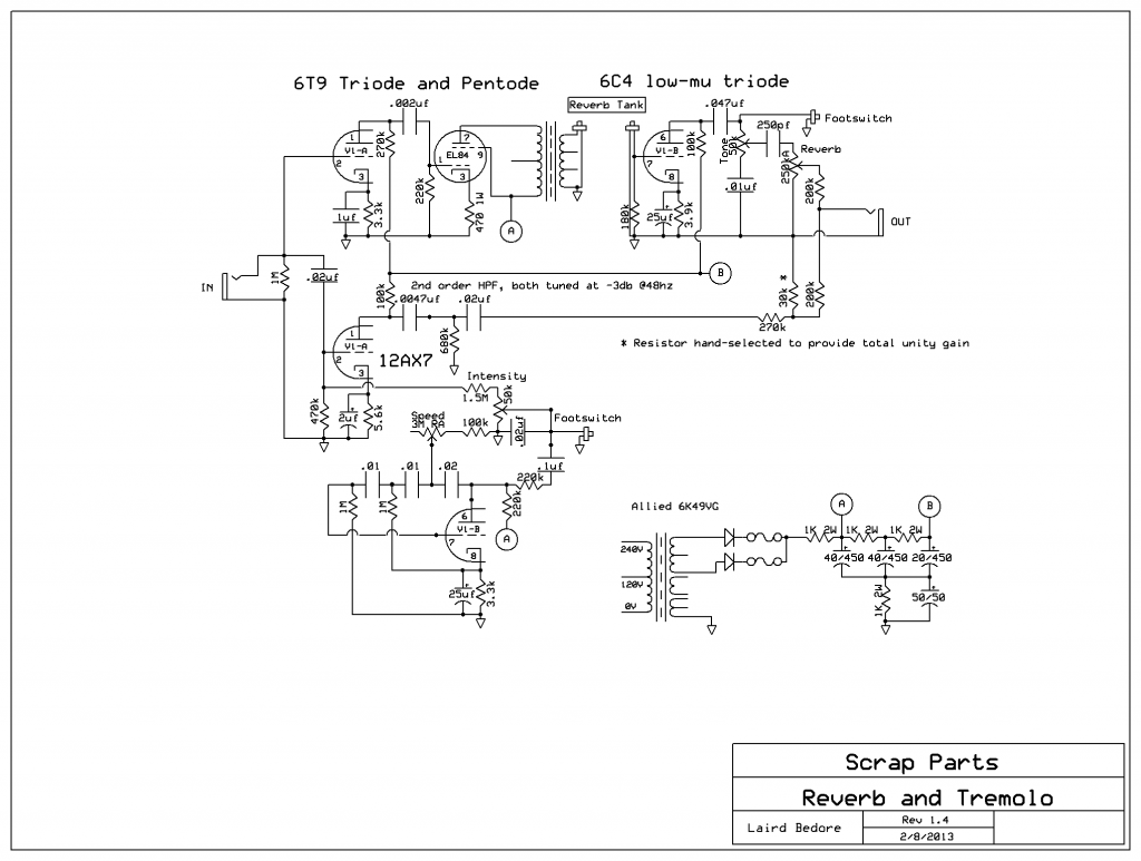
If I were building this from scratch and picking the tubes to use, I probably would have chosen an ECL82 (6BM8) instead of the 6T9. That said, the 6T9 worked wonderfully and took everything I threw at it, so if you have one handy, don’t hesitate to put it to use. I arranged the 6T9 triode as a gain stage before the 6T9 pentode reverb driver, and the 6C4 as the reverb recovery stage. This was pretty straightforward – use a big plate resistor to maximize linearity and gain, and a relatively small cathode capacitor to keep big low frequencies from “crashing” the reverb tank. Compared to typical guitar-amp type triodes, the 6C4 needs a larger cathode resistor to achieve the same bias, but otherwise it’s a simple gain stage followed by tone and volume.
The Tremolo
For the “dry” signal I used the 12AX7′s first triode, with the second triode working as a tremolo oscillator by feeding the input grid of the first triode. This is where things got a little touchy. First off, the oscillator was injecting a lot of nasty noise into the gain stage. I took a play from Jeff Gehring’s ReVibe and ran a .02uf cap to ground to shunt the noise. Next, the oscillator’s voltage output was in the 14v peak-to-peak range, which ran the gain stage way into cutoff on both ends of the spectrum. After experimenting with a number of different potentiometer and resistor combinations and arrangements, I used a 50K pot for intensity, pushing into a 1.5M/470k divider network (the bottom half of which doubled as the input grid ground reference). That got the tremolo intensity down into usable territory.
Fixing the Problems
At this point I realized that the tremolo oscillations are affecting both the dry and the wet gain stages. Although the effect was kind of cool, the oscillator would not stay stable. I had to decouple the inputs with a capacitor that would block most of the trem signal from reaching the wet channel. Add a 1M grid leak resistor and a .022uf cap, and now the tremolo is limited to the dry signal.
Once that was all worked out I discovered a new problem – the tremolo signal was being amplified and sent out the output! plugging the unit into a high-impedance input would cause the first stage of the target amplifier to not only oscillate, but run way past cutoff, causing dangerous overload conditions that could damage the amp. I tried adjusting the output coupling cap, but by the time I could get the tremolo problem reasonably under control I was killing the low-end frequency response. I needed a sharper frequency cutoff. With the help of a frequency calculator I arranged two high-pass filters in series, creating a second-order filter that cuts off at 12db/octave. I tuned the -3db “elbow” of the curve to hit at 48hz, ensuring that the low E note of a guitar (82hz) would go untouched (within 1db, at least), but even the highest oscillator frequencies should be attenuated by a minimum of 24db. This seemed to do the trick, and brought the trem signal on the output down to less than 300mv under the most maximal conditions.
Finally! A working oscillator and reverb circuit! I added the footswitch connections (the classic 2nd R/C leg in the oscillator and at the reverb tone input – I never footswitch the reverb before recovery because the footswitch noise gets amplified) and tested with my trusty old Fender dual footswitch – everything worked great, though I got a slight pop when disengaging the tremolo. Next I went on to testing with my Boss FS-6 footswitch. All of a sudden the tremolo intensity dropped and the frequency stability went to crap, and the reverb signal was significantly attenuated. The inductance and capacitance of the footswitch connections was messing with the circuits. The reverb was fixed by moving the footswitch connector before the 250pf cap feeding the tone, and the tremolo was moved to the middle lug (input) of the intensity pot. Now the choice of footswitch (and the length of footswitch cable) makes no effect on the operation of the unit.
Now that it’s working…
This project was made for Frankie as a “thank you” for the treasure trove of Hammond parts. He would be running this unit most of the time in the effects loop of his Marshall DSL. I don’t own any amps with an effects loop, so all of the testing and diagnostics I did were based on running the unit in front of the amp. It turns out my attempts to make this circuit tolerant of varying input and output impedances paid off, because it works even better in the effects loop than it does in front of the preamp. Now all it needs is a cabinet to house the chassis and the reverb tank and it’ll be ready to hit the road with the Cowboy Mafia!