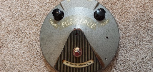
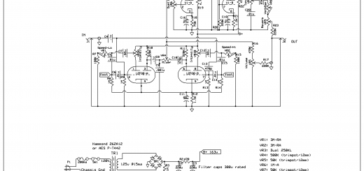
The idea behind the Revibe is brilliant: Take a standalone reverb unit and add the two-phase “harmonic vibrato” found in the 6G12 Concert.
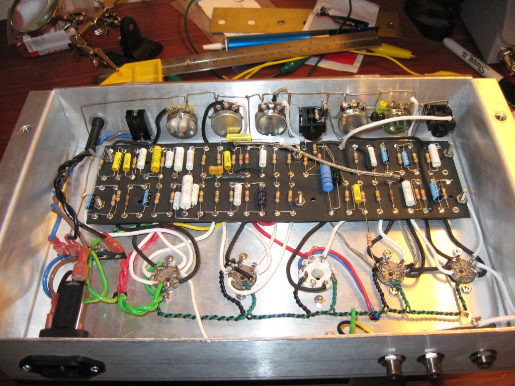
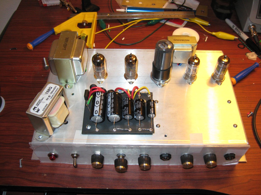
I first built this Revibe in 2010. I bought the fiberboard and power transformer from Weber, and used my own components for everything else. I modified the layout to fit a narrower chassis by relocating the power filtration section to a ‘doghouse’, but all the fundamental orientations remained the same as stock.
This is a really freakin’ cool effect to have, especially the two-phase tremolo! But there are a few adjustments that can really improve this project:
- I made some layout improvements. The position of the input and output jacks was reversed… I don’t know why they were ever recommended to be criss-crossed with unnecessary long connecting wires – putting the input at the edge of the chassis and the output directly next to its output connections is common sense. I also used Cliff jacks to guarantee chassis isolation and allow the sensitive connections to ground when the jacks are unplugged.
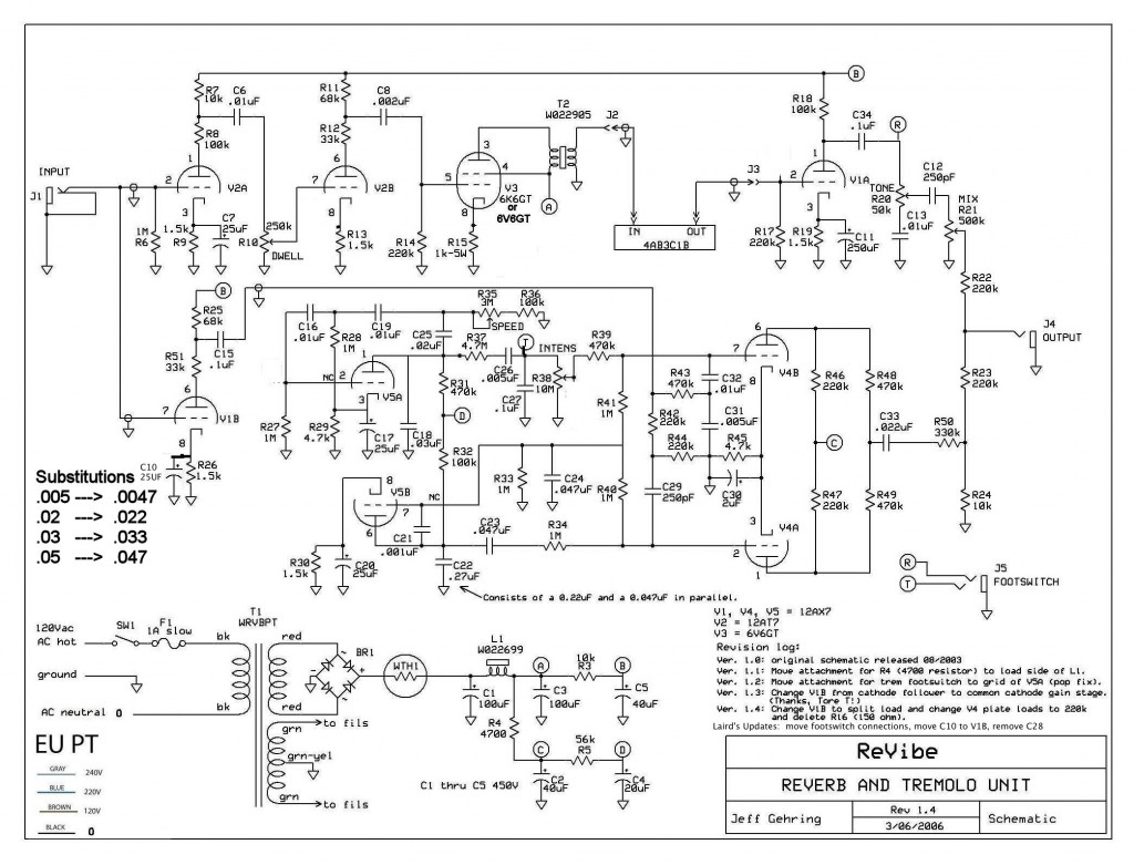
- I added an isolation network between the circuit and chassis/safety ground, like in Jeff Gehring’s Revibe V2 schematic. I never used the “brass plate” grounding scheme from the Weber layout – merging chassis and circuit grounds is a really bad idea when it comes to anything that will be subject to high gain (like a pre-preamp Revibe!) In order to complete the separation of circuit ground from the chassis I moved the reverb return’s 220K resistor (R17) to the fiberboard, next to the 1.5K/250uf cathode connection on V1A.
- The stock ReVibe gave me less than unity gain. To resolve I added a bypass capacitor to the cathode of V1B, parallel to R26. Another way to accomlish this is to change the values of R25 and R51 – making them both 47k or 51k would also increase the gain.
- Because I am using a “hot” 6V6 to drive the reverb tank, i was getting crashing during heavy input. As a cheap and dirty solution I lifted the cathode bypass cap, problem solved. Trialing less aggressive tubes or switching to a 6K6 would be a better solution. If you’re the type that uses a lot of boosting pedals and runs into this problem often you could try changing the balues of R7 and R8 to reduce the input gain.
- The tremolo stability needed some improvement. I removed C28 because it doesn’t appear to be necessary and it reduced the tremolo intensity. I moved the tremolo footswitch connection to the first lug of the Intensity pot. This greatly improved stability and switch-in delay when a footswitch is used.
- I moved the reverb footswitch connection to the first lug of the tone pot. This plus the grounding improvements substantially reduces the amount of noise and reverb attenuation introduced when using a footswitch.
With all of the “experiences” I have had with this Revibe unit, I would not build it again. As I learned with my junkpile 6T9 “Revibe” project, this effect can be built much simpler, smaller and quieter with less effort and less cost. I hope to come up with my own original “Revibe” design soon leveraging a 12FQ8 for asymmetric tremolo, a pentode/triode combo for reverb and at most one more tube.
Audio Clips
ReVibe Sample 1:
Tremolo only:
Reverb only:
Tube Lineup:
- V1 (gain and recovery): 1962 Raytheon Black Plate 12AX7
- V2 (reverb pre): 1970′s GE 12AT7
- V3 (reverb power): Ken-Rad/GE “VT107″ grey-bottle 6V6GT
- V4 (tremolo mixer): 1972 Westinghouse Japan 12AX7
- V5 (tremolo oscillator): 1962 Raytheon Black Plate 12AX7

