When you’re looking to build an amp on a budget, one of the hardest pills to swallow is the cost of a suitable power transformer. Wouldn’t it be nice if there was a cheap alternative you could pull from the scrap heap?
We all have probably owned more than one cheap consumer-grade UPS over the last decade. If we’re lucky we can replace the 12v batteries in it a few times and squeeze 10 years of life out of one, but eventually something goes wrong on the circuit board and the UPS is toast. When that happens, bust out the screwdrivers and wire snips and yank the transformer out of your old UPS!
WARNING!!
For safety’s sake we need to start with a few disclaimers. What’s described here can be EXTREMELY dangerous – most of the example circuits DO NOT provide magnetic/inductive isolation between mains and the circuit, so additional precautions must be taken:
- A 3-prong plug and outlet is ESSENTIAL.
- Ground should ALWAYS be TESTED – everyone should have an outlet tester! They’re only a few bucks and available at just about any hardware store.
- Voltage-doubling circuits are asymmetrical and actually depend on being able to run some current to ground. Because of this they don’t work right on GFCI-protected circuits and cause the GFCI breaker to trip. Yeah, that IS a little scary.
- If paranoid about mains wiring faults, use 2 mains fuses – one for hot and one for neutral.
- There is no substitute for knowledge – understand what you’re dealing with when building electronics!
With all that said… it’s not the transformer that is dangerous, it is operating with a wiring fault that’s the problem. Otherwise we would ban toasters, blenders, power drills, hair dryers – practically all household appliances! If you’re operating an amp somewhere with a bad/floating ground and/or reversed mains polarity, the electrocution you get will be potentially lethal whether you’re using a magnetically-coupled or electrically-coupled transformer. What is REALLY needed is an automatic protection mechanism that prevents the use of an incorrectly-wired or faulty mains supply.
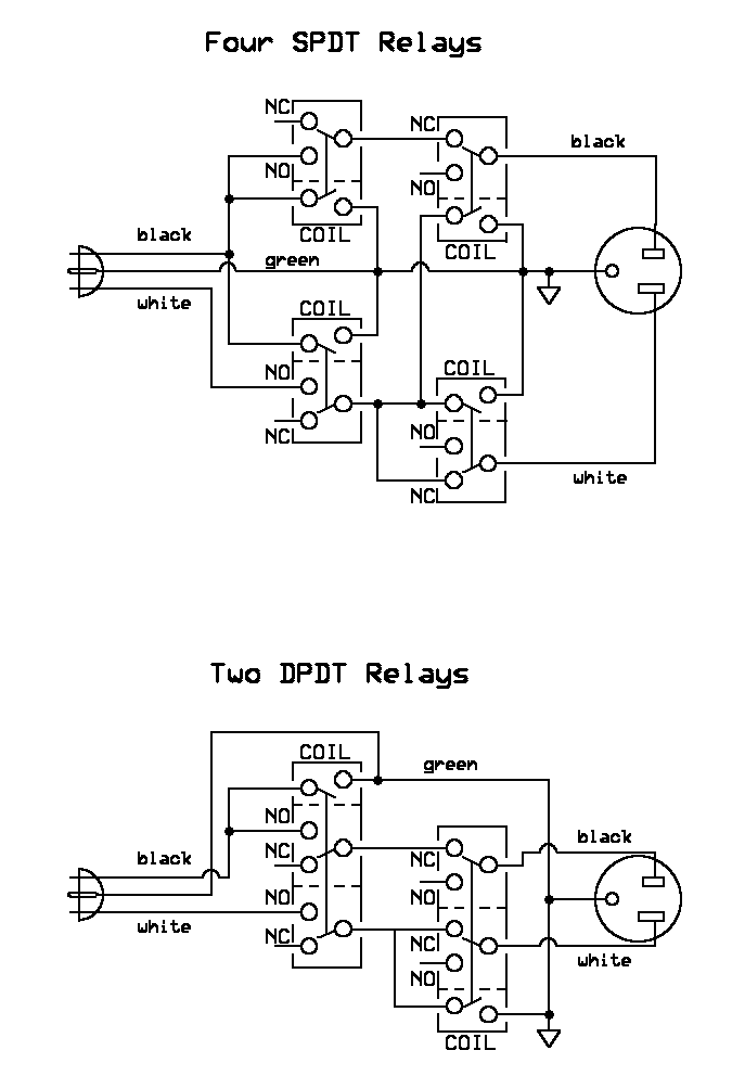
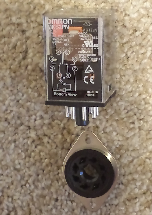 Another thing you can salvage from a lot of dead UPSes are 120V AC relays. What we’ll need are two DPDT relays or four SPDT relays. Stage 1 monitors the voltage between hot and ground – if it’s high enough to pull the coil, the relay connects hot and neutral through to the next stage. Stage 2 monitors the voltage between neutral and ground – if it’s high enough to pull the coil, the relay disconnects hot and neutral. If you have a variety of relays to choose from, stage 2 should ideally use a lower voltage AC relay – since ANY voltage between neutral and ground is bad, the lower the trigger voltage the better.
If you’re building from scratch and integrating the protection into the amp, these Omron MKS2P DPDT relays are very cool – they fit into an octal socket, so they can fit where your tube rectifier would have been!
OK – back to UPS Transformers…
Most consumer UPSes are based around the same design – there’s a 24, 36 or 48v DC battery array that, with the help of some solid state switching circuitry, is used to generate mains AC power in the range of 500 to 1000 watts. Practically every one has a big transformer with a 3-tap primary, providing a 1.125:1 step-up or step-down. Many of them have additional secondary windings that put out voltages ranging from 12v to 90v. With some creative circuit planning, these can make excellent power supplies for tube amp projects.
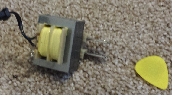
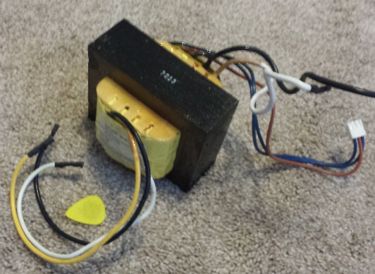
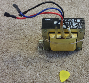 Here’s a transformer I pulled from an old 1400VA PowerWare UPS: it has a 3-tap primary and no secondary. The primary tap ratio is 1.125:1 and can be wired for step-up or step-down. If you’re using a 3-prong grounded power plug and you’re careful to make sure that the neutral connection is the one passed on to the rectifier, this type of transformer can safely be used to power the HT supply. The transformer core should be grounded for safety and a dual-pole power switch used to disconnect both mains legs from the transformer.
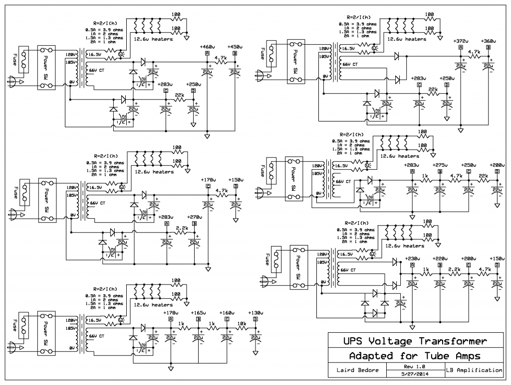
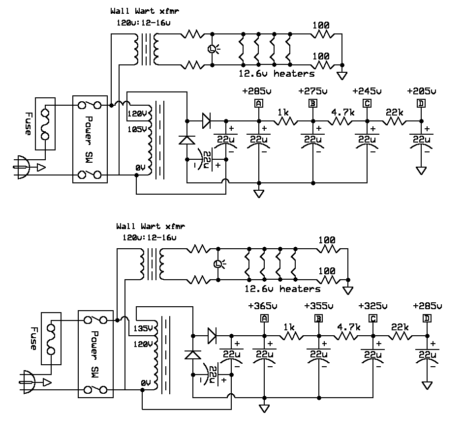
With the help of a voltage-doubling rectifier circuit and a wall wart transformer for heaters, the following basic designs are possible:
The actual voltage put out will vary depending on the load, the capacitor values, and the ESR of the capacitors. The capacitor and resistor values above are just examples – other values may be better suited to your particular project or implementation. There’s still a pretty decent amount of AC ripple at the A node – not a problem if powering a push-pull amp, but for single-ended output circuits it would be better to increase the filter cap values to 100uf or even higher.
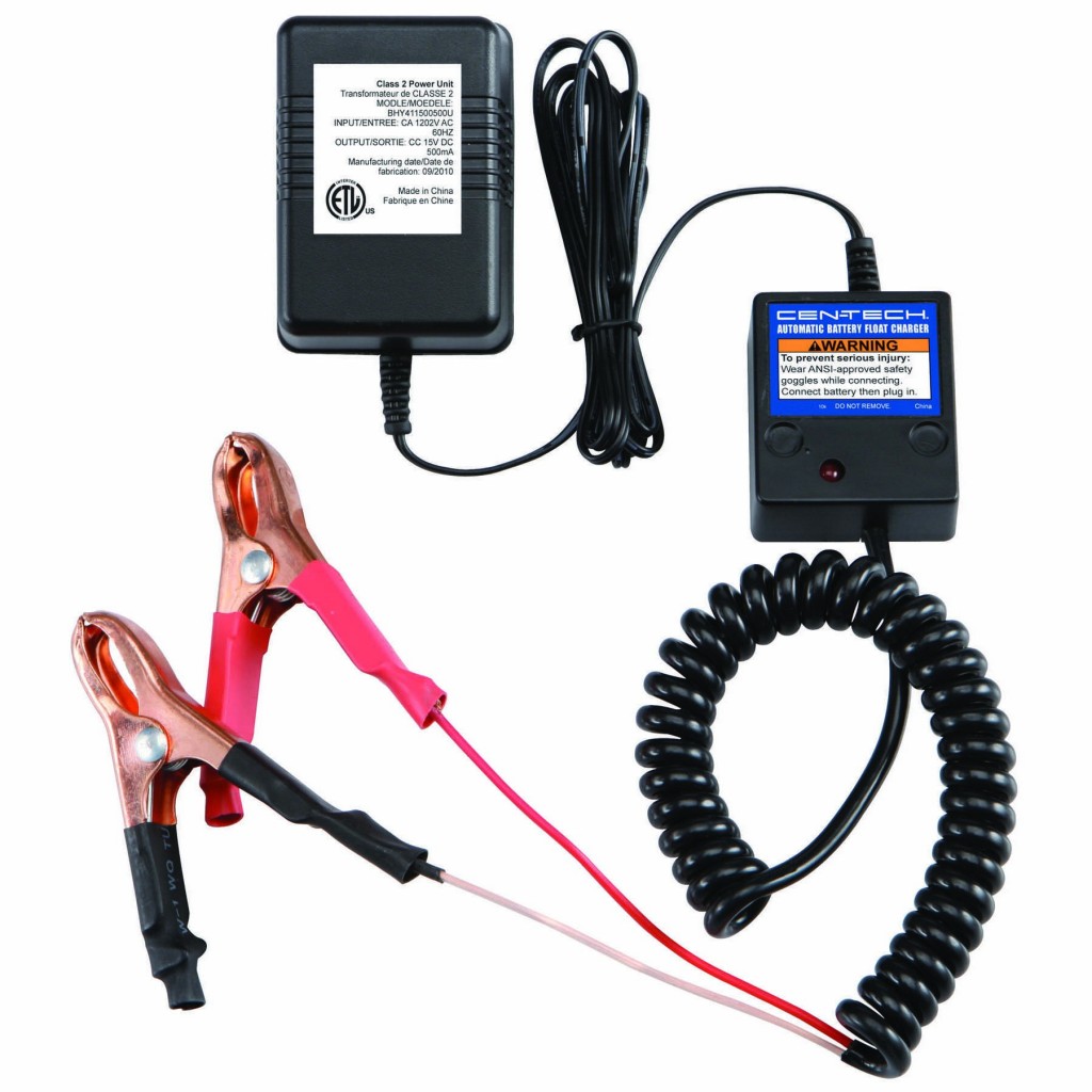
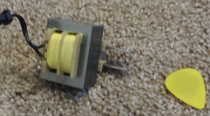 Speaking of wall wart transformers for heater filaments, one readily-available and cost-effective option is hiding inside this Automatic Battery Float Charger found at Harbor Freight. During their sale events this charger can often be had for $6 or less. The specs printed on the outside claim it puts out 15v DC at 500ma. After chopping off the rectification circuit I measured 14.6v AC at no load, with a DC resistance of 96 ohms across the primary and 2.8 ohms across the secondary. If it could sustain a rectified 15vDC @ 500ma, it can probably survive 12.6vAC @ 780ma – just enough to heat a pair of EL84s in series. Using one of these to heat the power tubes and another to heat the preamp, nearly any variation of 15-22 watt EL84 or 6V6 push-pull amp could be built. Dropping resistors may be needed to get the voltage to land at or near 12.6V.
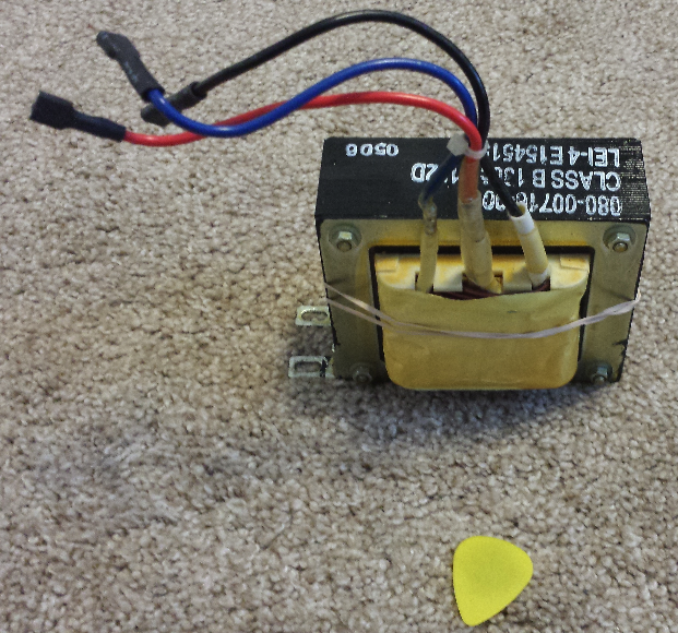
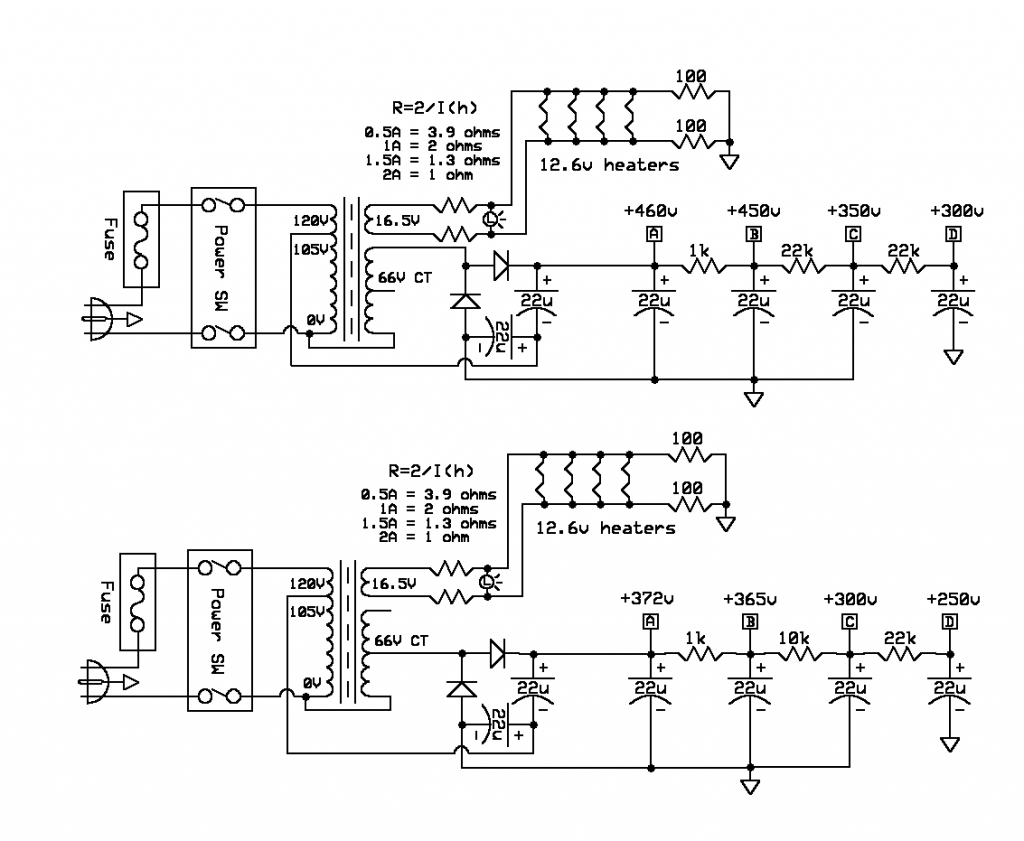
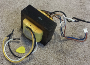 Now let’s look at some more complex options. Here’s another transformer, this one pulled from a mid-2000s APC UPS rated for 900VA. In addition to the 1.125:1 step-down primary, this one also has a 16.5v and a 66v center-tapped secondary, both of which were built for high current output. Conservatively the 16.5v is probably good for 5 amps, while the 66v is probably good for 1 amp. With some dropping resistors the 16.5v secondary could provide 12.6v for heater filaments.
With such high-current windings at our disposal, we can use quite a few tricks to generate a high voltage supply – voltage doublers, stacked secondaries, and all the combinations therein. Here are a few wiring options to achieve different B+ voltages using different rectification arrangements:
Another approach is to wire the primary and secondary in series to effectively create one higher-voltage winding. You may have to flip the secondary’s connections to get the windings in-phase with each other. In the case of this APC transformer, this can yield an ideal power supply for a 6L6- or 6V6-based amplifier just by changing the series winding connection:
Taking into consideration the low winding resistances, the size of the transformer core, the voltage doubling circuits and the original UPS ratings, I expect that any of these circuits should be good for at least 200-250ma, which is enough to power a 50-watt amp like a Bassman or Marshall. Some of the non voltage-doubled circuits should be good for even more current, perhaps 500ma to 1A!
There other circuit variations not discussed here – the input taps could be reversed for a step-up to achieve even higher voltages, and the 16.5v winding would become about 18.5v – perfect for doing three 6.3v heaters in series.
With a little ingenuity these otherwise-unwanted hunks of iron can make great power transformers for tube amps and save you a few bucks.

