Building an all-tube-powered 5.1 channel surround sound home theater system is probably the most ambitious project I have attempted. My goal is to build a surround sound home theater system using all tube amps, and to do it without bankrupting myself in the process. To pull this off I had to set a few guidelines that would keep this project under control:
- It should perform on par with a mid-range home theater system (100w/ch, 88db speakers… 108db rated sensitivity)
- It should cost on par with a mid-range componentized home theater system. $2,000 total price tag.
- This must be fully compatible with a modern home theater experience: digital audio inputs, remote volume control and input switching, Dolby AC3, DTS and ideally ProLogic decoding.
- Using new iron would break the bank, so salvaged amps are needed. There are plenty of cheap Chinese-made tube amps out there, but where’s the mojo, and how long are those crappy components going to last?
- The amp designs should require as little modification as possible to suit the purpose. Vintage amps should remain virtually stock to retain their character.
- The end product must be a visually-appealing showpiece without distracting from the home theater experience.
So there it is. Not just tube hi-fi on a beer budget, but SIX channels of home theater goodness, including speakers, tubes and all, for under two grand?!? Rest assured there won’t be any Jensen gold-wired 300B monoblocks in this system; this will be all about squeezing out bang for the buck.
Decoding
The first thing I had to figure out was how to decode digital audio and provide analog preamp outs on the cheap. There are a number of Chinese-manufactured DTS decoding units with full remote-controlled configurability sold under the brand names MOCHA and HLLY. The MOCHA X-3B is the latest in the company’s product line, and it is available with a US-compatible power transformer. There’s a unit manufactured by Hifi360.cn and sold under the brand names Hifi360, HLLY, LEMING and Fanmusic as the HF-D1A/HF-D1B. I found it being sold on eBay with a 120v/60hz input! It was SUPPOSED to have a 2v / 10v max preamp out switch, but the unit I received didn’t have it, and the eBay seller wouldn’t respond to repeated attempts to get the unit exchanged. That led to a shortage in preamp gain that forced me to abandon my original 5-channel design, but more about that later.
Speakers
Since this amp will only be pushing a maximum of 20 watts per channel, very high-efficiency speakers will be needed to provide an adequate listening volume of 108db. 20 watts will provide about +13db, leaving a requirement of 95db sensitivity for the speakers. I had originally set my sights on Klipsch’s RF-42 Reference series… A full set would have cost about $1,150 before tax. Then I tried to get a decent set of used Klipsch speakers, but price-wise it just wasn’t working out. Instead I went with BIC America FH series speakers for a grand total of $652!
- FH6-LCR center channel – two 6.5″ drivers and a 6.5″ aluminum horn tweeter… 95db sensitivity.
- FH-6T tower front channels – two 6.5″ drivers and a 6.5″ aluminum horn tweeter… 96db sensitivity.
- FH-65B surround channels – one 6.5″ driver and a 6.5″ aluminum horn tweeter… 95db sensitivity.
The Original Design
My original design was aimed around using minimally-modified Leslie amps to run the main channels. It would have been really cool to keep the original amps intact, but fate had a different idea.
When I disassembled the 145RV and 610 amps I discovered something interesting… the “EMI 025411″ output transformer from the 145RV and the three “6081″ output transformers from the 610 had not one, but TWO output taps. The OTs from the 610 had their black wire grounded and the yellow wire connected to output and NFB. However, a yellow/black striped wire came out inbetween but was tucked inside the housing, unused. On the 145RV, the yellow and black striped wire had been connected to output and the yellow wire connected to NFB. DC resistance readings show approximately 1 ohm (+/- 0.2 ohms) between black and yellow/black, and similarly 1 ohm (+/- 0.2 ohm) between yellow/black and yellow. Across the full winding from black to yellow read 2 ohms (+/- 0.2 ohms).
It turns out this yellow/black striped wire was an 8 ohm output tap! On the later Leslie models that used the “Type 061440″ reverb amplifier, leslie equipped TWO 6×9 speakers in parallel, providing a load of 8 ohms. Rather than build different reverb amps for different models, they simply connected the appropriate (8 ohm or 16 ohm) output tap depending on if the amp came with one or two 6x9s. Good for me, now I can use the 8 ohm tap for output and the 16 ohm tap for NFB!
The Revised Design
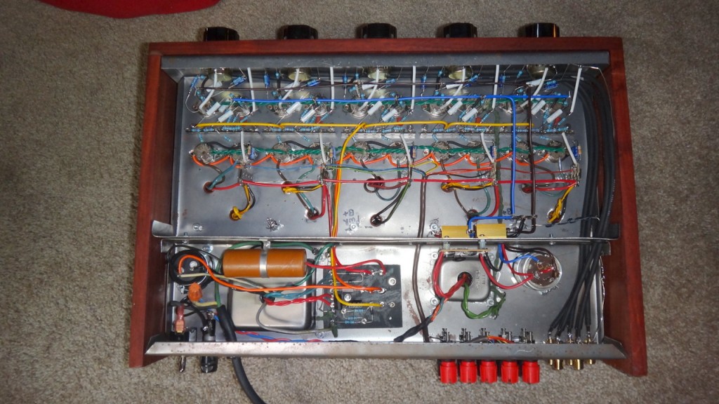
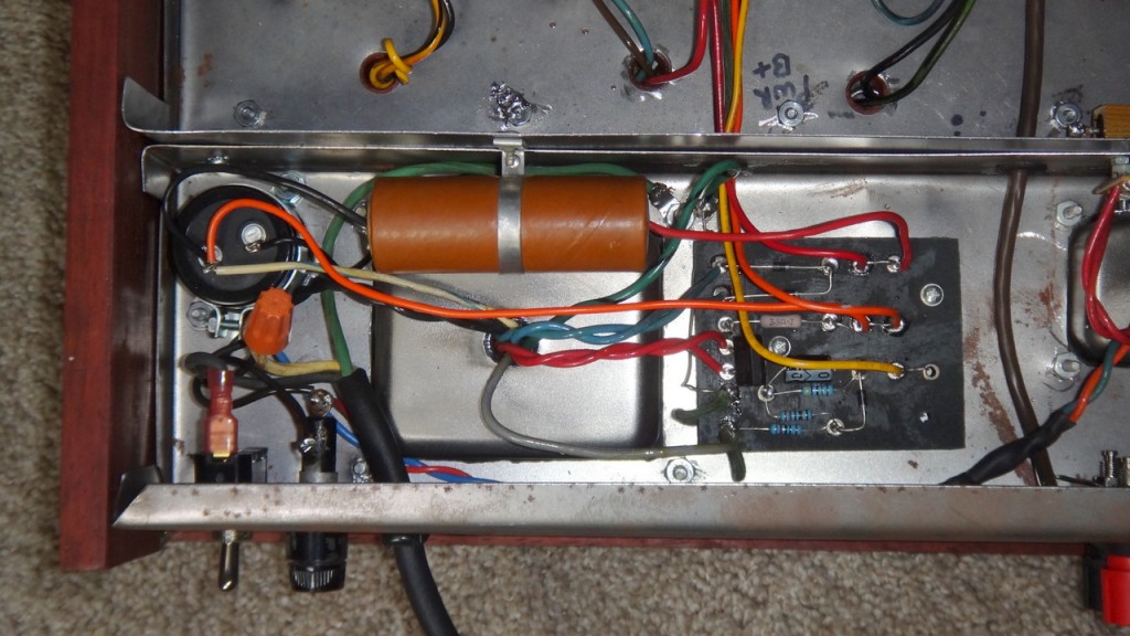
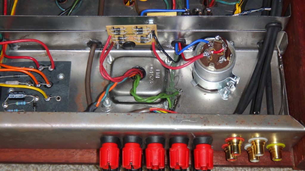
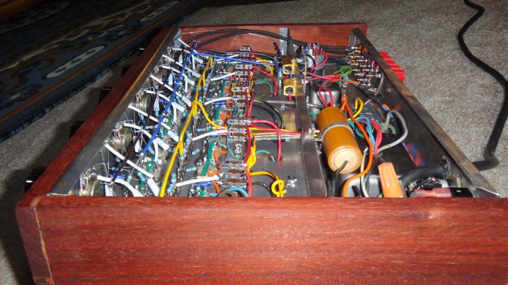
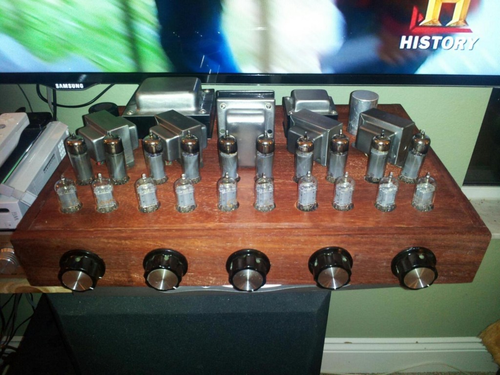
With all this great iron and a beautiful stack of fully operational RCA tubes, I designed a single chassis to house all five channels. To make it fit in with the home theater experience I made it 18″ wide – close to the industry standard of 17″ to match the cable box and blu-ray player. Thanks to my friend Rich I got my hands on some incredible African Padouk hardwood to make the cabinet, which wraps around a two-chambered chassis made from two sheets of 22ga steel and a cheap Harbor Freight metal brake. The rear chamber contains the power transformers, rectifiers and capacitors while the front chamber contains the output transformers, audio circuitry and the tubes up front. There is a large volume knob in front of each channel on the face, the only controls on the amp.
Chassis Layout
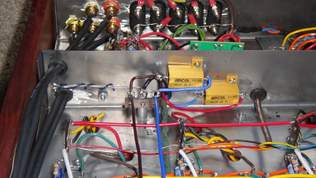
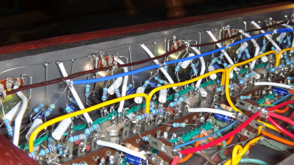
Forget the original diagram, here’s the actual amp. It’s an exercise in common sense: maintain the maximum possible distance between AC power and inputs/preamp. Use quality shielded cable with a relatively large coaxial diameter (to reduce capacitance effect) for the long input runs. The power runs are all “floating”, so they’re as far as possible from the signal path. Avoid arranging signal components in parallel. Do not chassis ground either the inputs or outputs, as that will create a ground loop and introduce hum. Since there are two power transformers, use a star ground topology for the preamp and a separate star ground for the power amp, and do not interconnect them.
Schematic and Circuit Layout
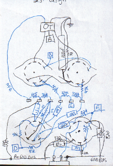
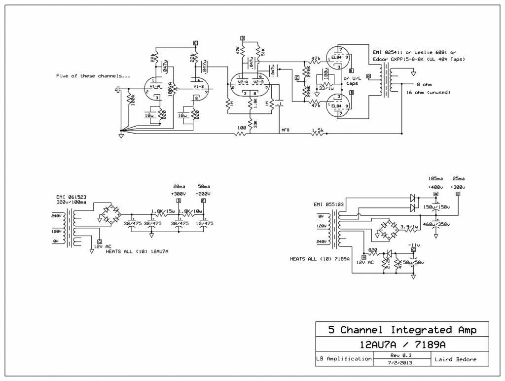
The circuit is all about simple, progressive gain stages. The added gain stage in the front is mitigated through the adjustable 100k volume pot, and the move to a long-tail phase inverter allows for much greater negative feedback, improving linearity and reducing distortion. I kept the hybrid fixed/cathode bias on the power stage but added big grid stoppers to help tame transient spikes, which are common in movies and TV shows.
Although I show the NFB coming off the 16 ohm tap in the schematic, I found that in practice the 8 ohm tap provided enough negative feedback, so I left it alone. ![]()
One BIG disclaimer here: Do NOT use regular EL84s at these voltages – if you’re lucky they’ll last about 10 minutes before suffering a really ugly and dangerous death. Run either genuine old-stock 7189, Russian 6P14P-EV (emphasis on the EV), or Sovtek EL84M tubes – they are made to withstand the 400v this circuit delivers. According to the GE 7189A datasheet from 1958, this circuit arrangement (400v plates, 300v screens, mostly fixed bias) should yield a maximum power output of 24 watts at 4% THD.
Here’s the first drawing I did of the final component layout. The final amp followed almost exactly this arrangement, with the exception of the power tube cathode connection, which was moved to the other power tube.
Cost
This revised design made maximum use of existing equipment but I still ended up spending $150 to cover the sheet metal, tube sockets, knobs, pots, resistors, capacitors and wire. That kicked up the 5-channel portion to a total cost of $400, but I can’t complain with a purpose-built and beautiful tube amp that cost just $80 per channel.
Here it is, finished and working!
The first question everyone asks: How does it sound? Great, especially considering the extremely low budget and recycled iron! I’m getting plenty of gain at 12 o’clock on the volume knob. My normal listening volume is about “25-30″ on the decoder for most TV shows and 35-40 for quieter movies. The loudest programs (like rock music) don’t start distorting until 50-55, and 60 is the decoder’s max, so there’s more than enough headroom for its intended use. The noise floor is extremely low, only audible within 6 inches of the speakers. What 60hz hum exists is completely unnoticeable unless the volume pot is turned up to the 3 o’clock position.

