


Like most things in life, I never want one of anything. One computer, one guitar, one motorcycle… No, I want that British chime. I want that pentodey grind. I want a Vox. So I built one!
Quite possibly my most successful custom amp build is my AC15-inspired head. But it didn’t start out that way… it wasn’t built from a kit, broke a lot of rules, went through a lot of changes and fixes and trial-and-error, but in the end turned out to be the best-sounding amp I have built to date. I want to share some of the ups and downs to help, inspire, inform, scare and entertain those of you interested in building a Vox-inspired amp.
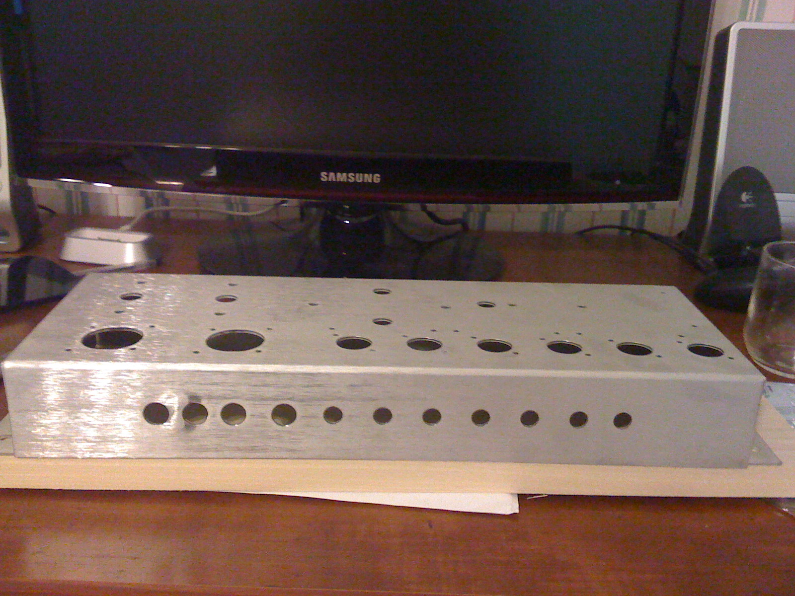
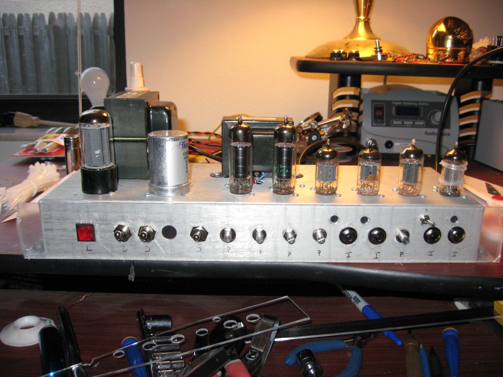
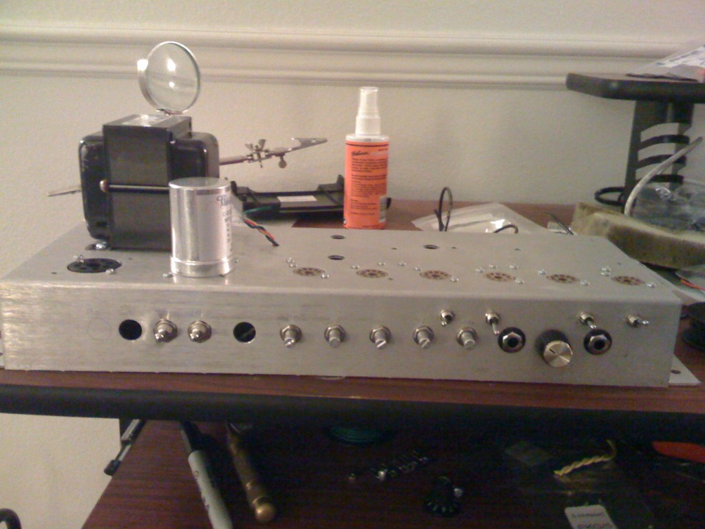
It all started in 2009 when I spotted an pre-drilled chassis I picked up for $20 on eBay. Two octal-sized holes, six 9-pin holes and pre-drilled holes for OT, PT and maybe a reverb driver littered the top, but they were positioned at the front of the chassis instead of the back. Four 1/2″ holes and seven 3/8″ holes lined the front. My best guess is that this had been intended for a Marshall 18-watt style build with cap cans in the octal holes.
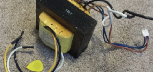
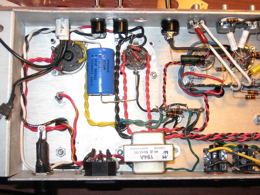
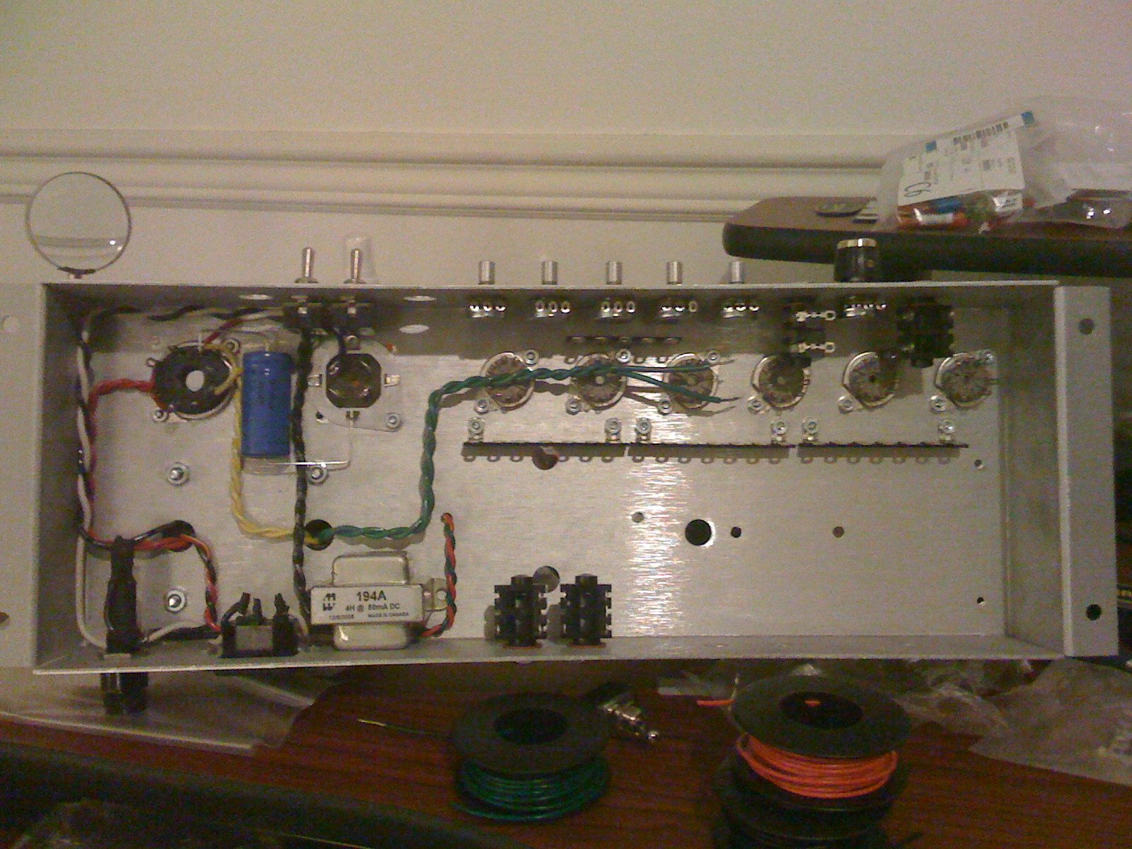
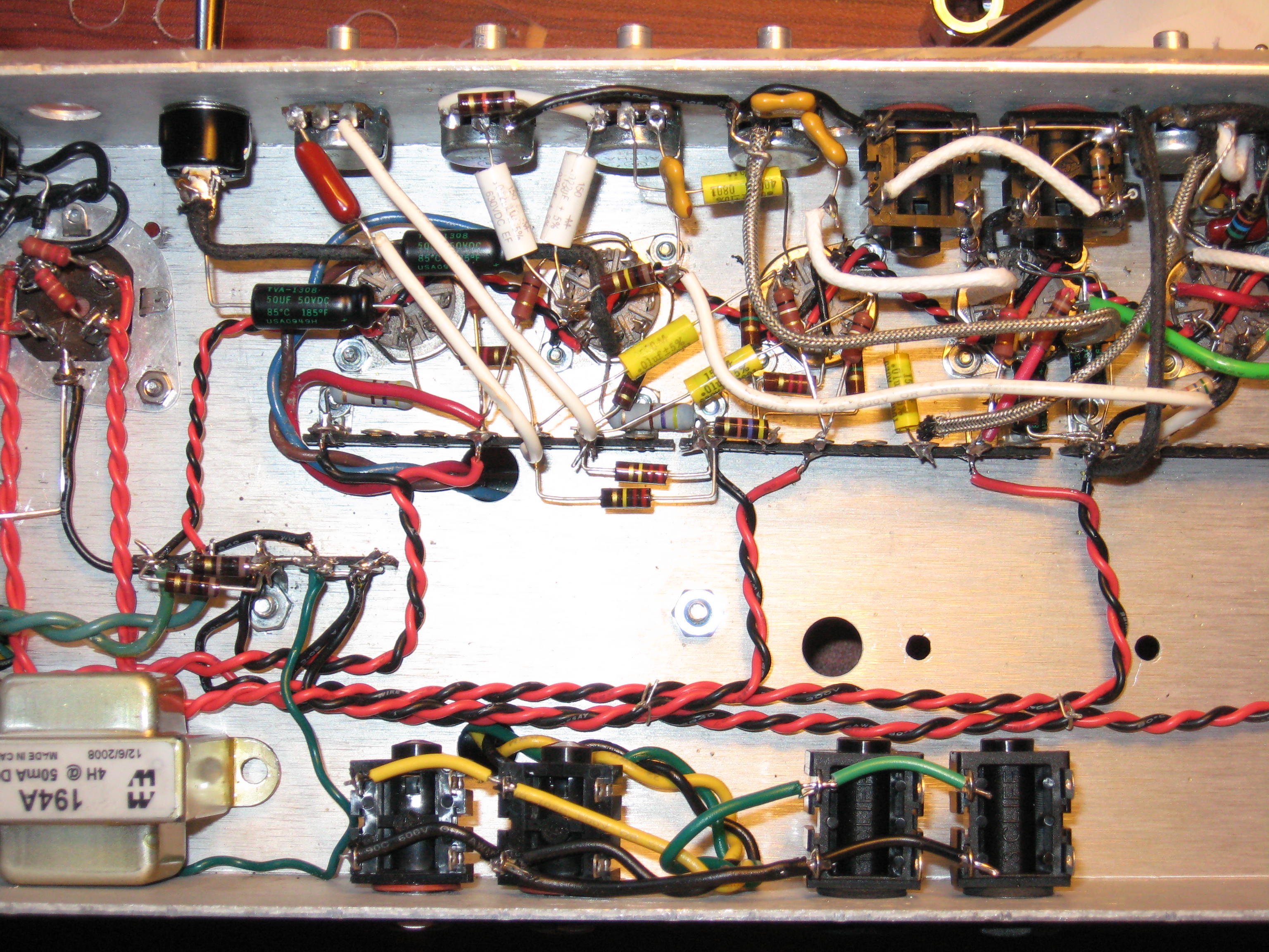
The first thing I did was measure the transformer mounting holes and look for transformers that would fit. The Hammond 272BX fit the hole pattern and met the voltage and current specs common to many AC15 replacement PTs, with the exception of the filament current. There wasn’t enough current for heating an EZ81 rectifier typically found in an AC15, but there was a 5V/2A winding. And I happened to have an extra 5Y3GT sitting around. Problem solved! I thought briefly about placing a choke in the pre-drilled holes on the far side of the OT and then decided against it, preferring to place the choke inside the chassis next to the rest of the power supply. I didn’t want long wire runs carrying mains AC hum to cross the OT and come so close to the preamp. The Hammond 194A choke fit the bill.

Next came rectification. Most Vox designs I could find indicated small capacitor values and a branched B+ feed. Since I had an octal hole to fill I went with a 4-section cap can, 20-10-10-10. 10uf for each of the preamp branches, 20uf for the spot after the choke. Originally I put a 20uf/500v cap before the choke but later changed it to 30uf.
5Y3GTs aren’t exactly known for allowing huge reservoir capacitors or behaving nicely with current surges caused by standby switches, so I decided I would place my first capacitor before the standby switch to avoid the “big inrush”. The output transformer is fed from the far side of the standby switch. I added a reverse-bias diode in parallel with the choke to quell any potential flyback voltages that could occur when toggling the standby (not pictured). The end result is a useable standby that doesn’t run the risk of blowing either the rectifier or the choke.
For output transformer I originally went with an Allen Amps TO22, with 4 and 8 ohm outputs. Due to a brain fart I had when building my 6G2ish Princeton I later swapped in a 20-watt Hammond 1750H with only an 8 ohm output. I didn’t detect any difference in tone or quality between the two – they both sound great.
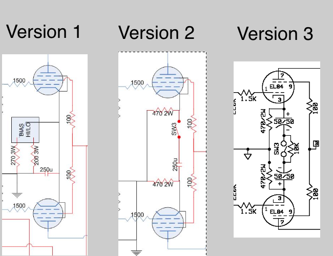
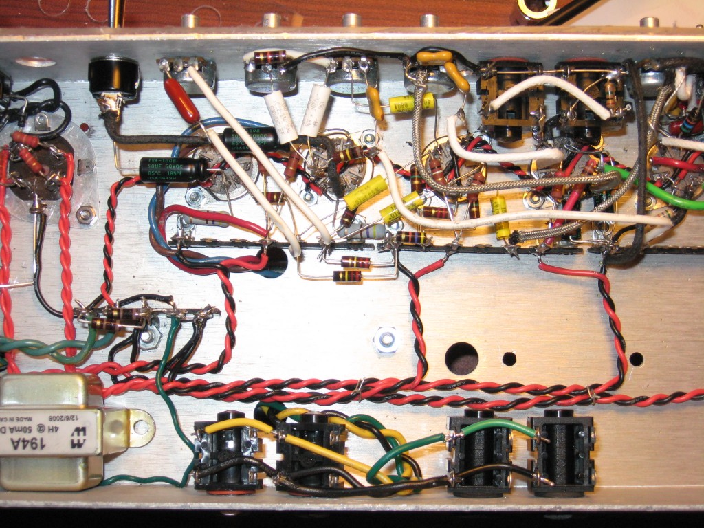
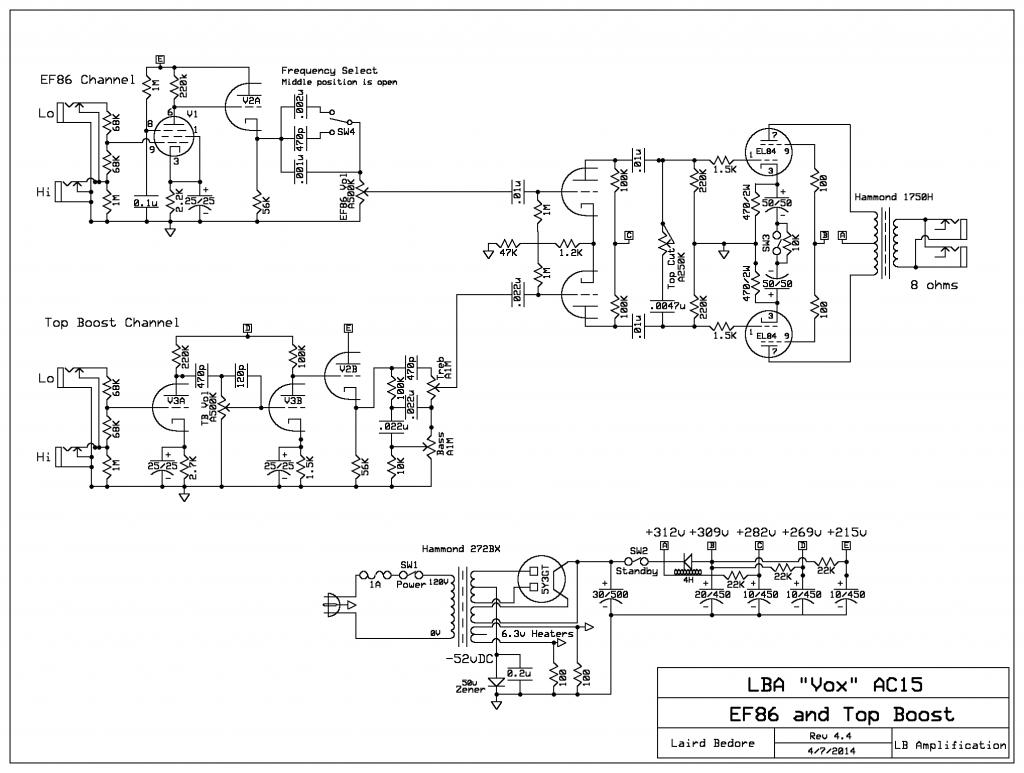
I started by building the PI and output section according to original AC15 designs – 47k long tail, 1.2k bias resistor, 100K plate resistors, top cut control, 1.5k input grid stoppers, 100 ohm screen stoppers fed from the same B+ as the OT, and a 130 ohm shared cathode resistor. The power dissipation was way too high – around 14W per tube – with a B+ around 360v. Considering my B+ was already much higher than the tubes or design called for I put in a high/low bias switch, switching between 200 ohms and 270 ohms. There was an audible difference between the two settings if you A/B’d them, but otherwise you couldn’t really tell them apart. After about 2 years I took a different approach: I cathode-biased each tube separately and switched a large capacitor between the cathodes. When the capacitor is out of the circuit the two cathodes can “float” on AC, which significantly reduces their push-pull efficiency. This proved to be a very effective high/low output switch, but simply switching the capacitor in and out would cause a large pop. I later replaced the one capacitor with two 50uf caps, their negative sides linking at the switch. a 10K resistor was paralleled over the switch, allowing the caps to maintain a nominal charge and eliminate the popping when toggling the switch.
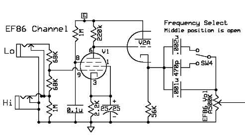
Channel 1 has always been an EF86, but it has seen all sorts of variations. It had one input jack with a high/low switch, a pentode/triode switch, a pentode “squish” control, a scoop-style tone control, a cathode follower… The end result is a standard two-jack input into a pentode-only EF86 using standard Vox values, heading out into a 12AX7 cathode follower with a 56K cathode resistor. Then it heads to brilliance/brightness/bass select switch with three settings: 1nf, 1.5nf, and 3.2nf. Last is a A500K volume pot, then coupled to the phase inverter using a 10nf (.01uf) cap.
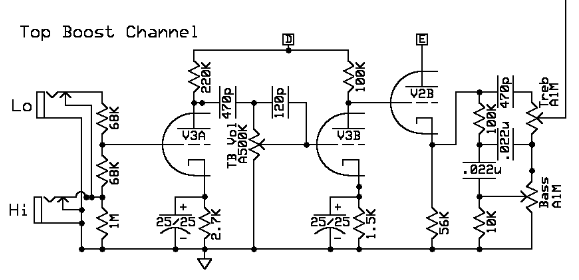
Channel 2 was originally going to be a Normal And/Or Top Boost channel. The Normal was dull, the Top Boost was great, and running them in parallel was nice and raunchy. But the gain difference between the two was significant, and the blend/mixing controls (whether it was a pot or resistors and a switch) sucked some life out of the tone. Eventually I got sick of all the fiddling, wired up a standard two-jack input, sacrificed the Normal channel and rearranged the triodes so one 12AX7 was dedicated to amplification and the other was dedicated to cathode followers for the two channels. In the end it has become a pretty faithful-to-the-original “bright side” Top Boost circuit with the classic 2-knob Vox tone stack. The TB channel rides a 22nf (.022uf) cap to the second (often unused unused) input of the phase inverter.
When I fixed the power tube cathode bias the B+ crept from about 350v to about 365v. The voltage was just too high, and the amp was sounding harsher than it should. I put a 50v zener diode underneath the HT center tap (physically it’s acting as a PT mounting bolt) bypassed with a 0.2uf capacitor (not pictured), bringing the B+ down to the 310v range these amps were intended to have in the first place. Lowering the B+ sweetened up the Top Boost a bit, but it made the biggest difference on the EF86. The lower voltage really brought the musicality of that tube to life!

As far as tubes go I have settled on the following as my favorite arrangement.
- V1: Philips Miniwatt EF86
- V2: Tesla (JJ) ECC803S long-plate (cathode followers)
- V3: Amperex 12AX7, 1970s (Top Boost)
- V4: Westinghouse Japan 12AX7, 1970s (Phase Inverter)
- V5,6: JAN Sylvania EL84s, late 1970s
- V7: GE 5Y3GT, mid-1960s
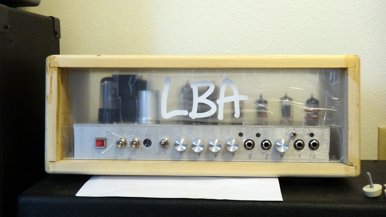
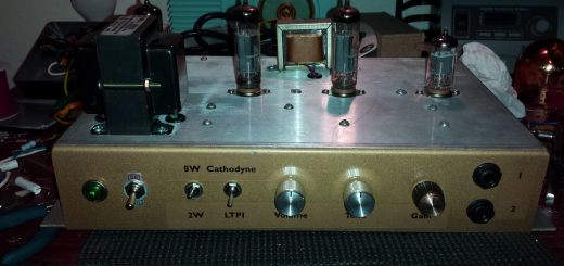
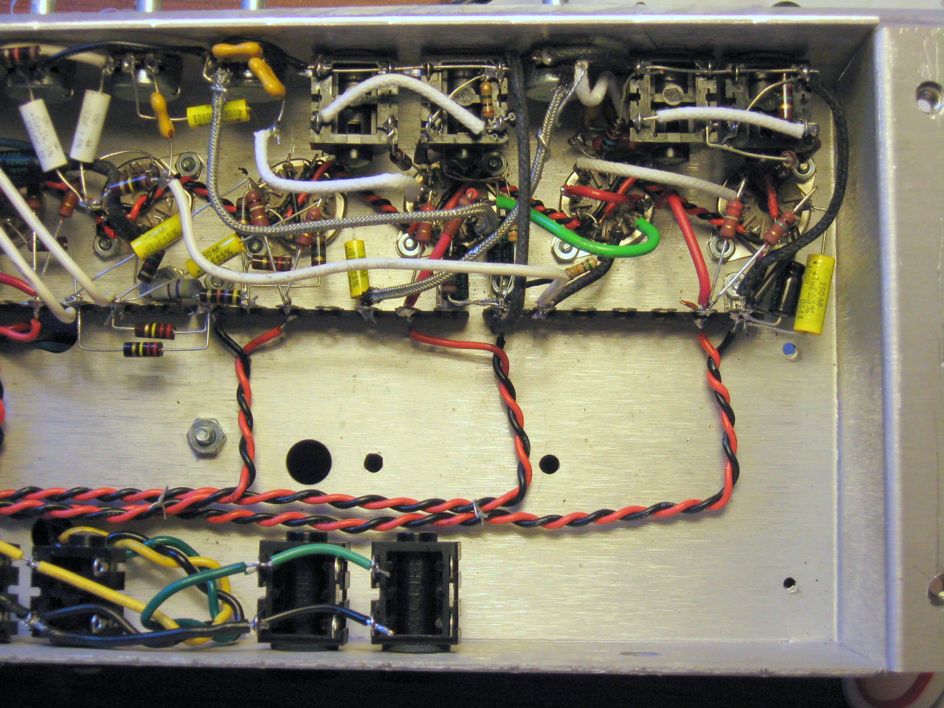
The amp has been electrically “done” for about 3 years now – I am too happy with how it sounds and how it runs to make any more changes. Plus, working on this VERY front-loaded point-to-point circuit is torture! Cosmetically I made a plexiglass front face and built a little poplar cabinet with a plexiglass front (to show off the tubes). I designed and had made a nice vinyl faceplate decal to go on the plexiglass, but I lost it during some house construction… and the company that made it for me went out of business. Since then I haven’t been motivated enough to tolex the cabinet even though I have a roll of blonde sitting around.
If I were to do it all over again, here are the things I would either do or consider doing differently:
- The power transformer!! Pick one with a 520-530vCT secondary if sticking with a 5Y3, or a 500vCT secondary if going with an EZ81/6CA4. A 4A or higher rated 6.3v heater winding would be needed to switch to an EZ81 recto.
- A better ground scheme. My ground scheme for this amp sucked.
- A rotary switch for EF86 channel frequency selection. In an ideal world I’d like to have 5 positions ranging from 1nf to 3nf in 0.5nf increments. 1.5nf or 2nf is my personal sweet spot though strats could benefit from a little more oomph.
- Shock-mounted/isolated EF86 socket. Although this one particular EF86 is forgiving when it comes to microphonics, my others (and most others) are not.
- Elevated heaters. I connected mine to ground out of laziness.

- Nice to have: DC Heaters for the first two preamp tubes. The EF86 and a 12AX7 together only use half an amp at 6.3 volts so it’s not too hard to do.
- Maybe: variable voltage regulation for the output tubes instead of the high/low output switch. This would also make the PT selection less critical since the voltage could be dialed down.